Channel Settings
You can make basic settings for each channel in WinDarab.
For each individual channel following settings are provided:
- Description
- Format (numerical)
- View Min
- View Max
- Signal (signal curve format)
- Separate Bits
Making Channel Settings
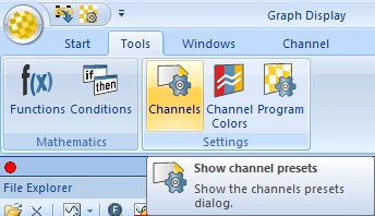
Select “Tools→ Settings→ Channels” in Darab Ribbon to open the “Channel Settings” dialog box.
The Channels are divided into five channel types:
- Measurements channels
- Math channels
- Virtual channels
- Internal channels
- Temporary channels
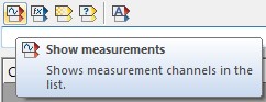
Click on Show measurements button to select and display the Measurements channels list.
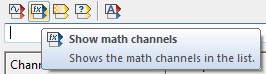
Click on Show math channels button to select and display the Math channels list.
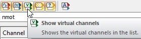
Click on Show virtual channels button to select and display the Virtual channels list.
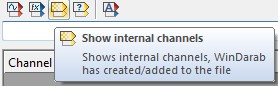
Click on Show internal channels button to select and display the Internal channels list.
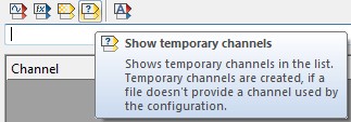
Click on Show temporary channels button to select and display the Temporary channels list.
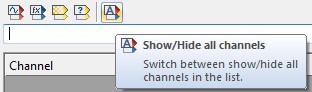
Click on Show/Hide all channels button to (de-)select and display/hide all channels.
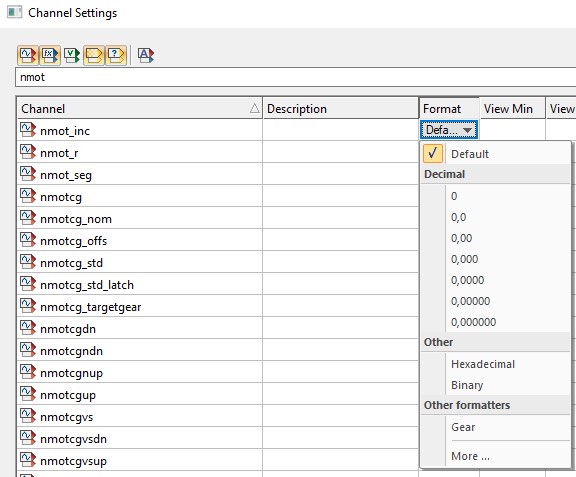
Channel Format
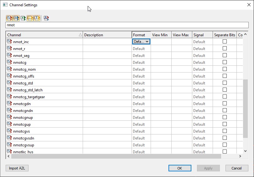
For each channel in the lists the following settings can be defined:
Description | A description for the channel can be entered in the text field. |
Format | Define the display format of numbers. |
Other Formatters | These can be used to show text representations of the data. This is useful when the channel value is an error code that corresponds to a text value |
The following formats are provided in the Format combo box of each channel:
Channel Visualisation
View Min | You can enter the value displayed as minimum for the channel. |
View Max | You can enter the value displayed as maximum for the channel. |
Signal | Determine the format for display of the signal curve. |
The following formats are provided in the Signal combo box of each channel: | |
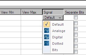
- Analog - values are interpolated.
- Digital - sampling points are represented by square wave signals.
- Dotted - each sampling point is represented by a dotted line.
- Bits - each channel bit is interpreted as a separate signal and represented by a square wave signal.
Separate Bit | With this option selected, single bit channels will be created for each bit of the measured channel. If selected each single bit will be shown as a channel. |
You can now select each one of these bit-channels individually in the channels pane.
Importing Descriptions
WinDarab enables you to import description for channels from a (named) object store.
Follow these steps to import a (named) object store:
- Open the “Channel Settings” box by using the “Tools→ Settings→ Channels” menu item.
- Click on “Import OSP/A2L”.
- Now select the (named) object store that contains the descriptions and click “OK”.
- The descriptions will now be imported.
- Click on “OK” to close the “Channel Settings” dialog box.
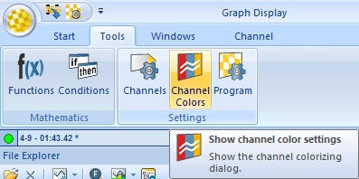
Channel Colors
Select “Tools→ Settings→ Program” to open the Channel Colors Dialog
This dialog allows you to assign different colors for different overlays to specific channels. The number of overlay-columns in the dialog equals the number of overlays in the File Explorer.
Automatic is recommended. When left in this mode, WinDarab will automatically choose a color for the channel that has a good contrast to the selected color scheme.
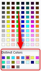
New Colors
Oscilloscopes and XY plots can get very busy when multiple signals are added. We have added 20 distinct colors to help.
Customize
These colors can be customized in setting.ini.
[Options]
DisinctColors= 0xe6194b, 0x3cb44b, 0xffe119, 0x4363d8, 0xf58231, 0x911eb4, 0x46f0f0, 0xf032e6, 0xbcf60c, 0xfabebe, 0x008080, 0xe6beff, 0x9a6324, 0xfffac8, 0x800000, 0xaaffc3, 0x808000, 0xffd8b1, 0x000075, 0x808080, 0xffffff, 0x000000__
Here’s an alternative set of colors:
DistinctColors=0xa6cee3, 0x1f78b4, 0xb2df8a, 0x33a02c, 0xfb9a99, 0xe31a1c, 0xfdbf6f, 0xff7f00, 0xcab2d6, 0x6a3d9a, 0x8dd3c7, 0xffffb3, 0xbebada, 0xfb8072, 0x80b1d3, 0xfdb462, 0xb3de69, 0xfccde5, 0xd9d9d9, 0xbc80bd, 0xffffff, 0x000000