Instrument Panel
The Instrument Panel is a window used to visualize data at the current cursor position.
Settings
Instrument Panel settings can be edited/loaded/saved using the F5/F6/F7 function keys (like many other windows).
Element Selection/Placement
- Instrument panel allow to select multiple gauges by pressing the Ctrl + Left Click or using a rubber band.
- The location and size of all selected gauges can be adjusted in a single step.
- Copy and paste of the selected gauges is supported
- The layout grid is removed. Now the borders of the gauges act as magnetic lines making it easy to align/adjust gauges.
- If multiple gauges are selected, the arrow keys can be used to move the gauges by pixel (without snapping to the magnetic lines). Additionally, the arrow keys can be used with Shift to align all gauges to the top, left, bottom or right border, together with Ctrl the size can be adjusted (Ctrl+Right Arrow, Ctrl+Down Arrow) or aligned and sized (Ctrl+Left Arrow, Ctrl+Up Arrow)
Elements
The elements that can be used on an Instrument Panel are:
- Value Display
- Bar Display
- Round Scale
- Bit Panel
Value Display
 []
[]
Value Display Common Settings
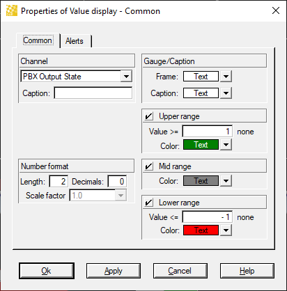
The Value Display can be configured with the following settings: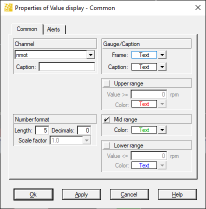
- Channel: Defines the channel data that the element will present
- Caption: Allows an alternate 'channel name' to be displayed
- This is useful in the event the measured channel name is not descriptive / long.
- Number Format: Defines the number of digits, number decimals, and scaling that will be used
- Gauge/Caption: Control the base colors of the display element
- Upper/Mid/Lower Range: Control the color of the display element based on the current cursor position value of the channel.
Value Display Alert Settings
The Value Display can be configured to visually alert the user based on the channel value.
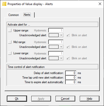
- Hysteresis: the value the channel must change in order to clear a triggered alert
- Example Engine Water Temperature: Hysteresis value = 2 and Upper range = 100
The Alert will trigger when the channel value goes above 100
The Alert will clear when the channel value goes below (100 - 2) = 98 - Upper/Mid/Lower Range: Toggle alerts based on the values on the Common Settings screen.
- Time Controls: Define time based automatic clearing of alerts or retriggers.
Advanced Value Display Usage - PBX Output
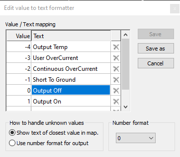
Value Displays can be configured to show an enumeration of the channel. This can be very useful for error channels where a text value is more descriptive than an error code.
Tutorial:
- Enter the Tools → Channels Settings Window
- Select the channels of interest (in our case PBX Output State)
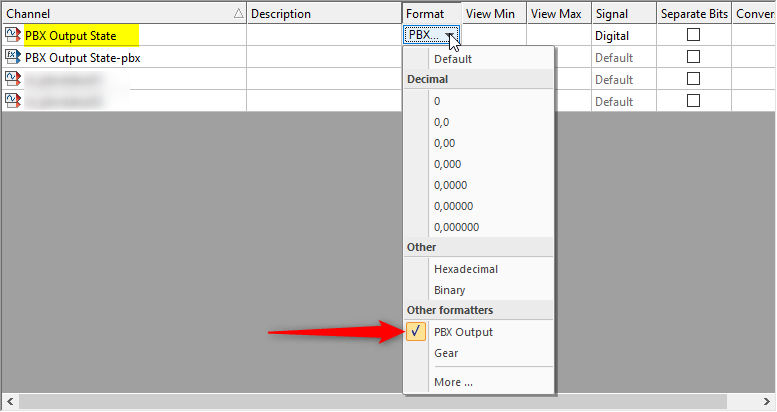
- Change the 'Format' cells to 'Other Formatters -> More'
- Create a channel formatter for PBX Output States
- Add the channel as a Value Display to your instrument panel
Pitfall: The formatter is a global setting, so if you go to an Oscilloscope and change the Channel Format back to display a number, your instrument panel will also change back to a number.
Bar Display

Bar Display Common Settings
The Bar Display can be configured with the following settings:
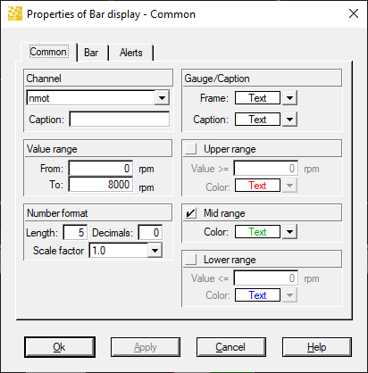
- Channel: Defines the channel data that the element will present
- Caption: Allows an alternate 'channel name' to be displayed
- This is useful in the event the measured channel name is not descriptive / long
- Number Format: Defines the number of digits, number decimals, and scaling that will be used
- Gauge/Caption: Control the base colors of the display element
- Upper/Mid/Lower Range: Control the color of the display element based on the current cursor position value of the channel.
Bar Display Settings
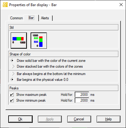
- Orientation: Select between Horizontal and Vertical layout
- Shape of Color: Drawing controls for the Bar Display
- Peaks: Controls for visual indication of min/max values
Bar Display Alert Settings
The Bar Display can be configured to visually alert the user based on the channel value.
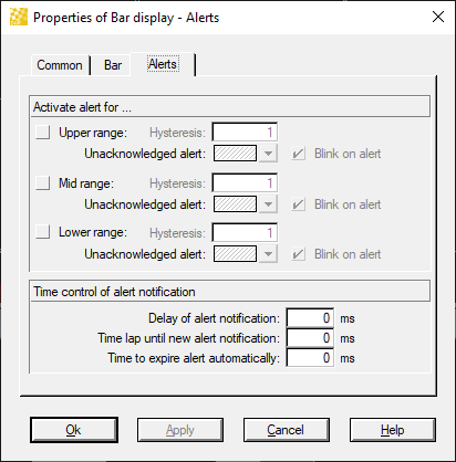
- Hysteresis: the value the channel must change in order to clear a triggered alert
- Example Engine Water Temperature: Hysteresis value = 2 and Upper range = 100
The Alert will trigger when the channel value goes above 100
The Alert will clear when the channel value goes below (100 - 2) = 98 - Upper/Mid/Lower Range: Toggle alerts based on the values on the Common Settings screen.
- Time Controls: Define time based automatic clearing of alerts or retriggers
Round Scale
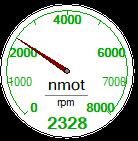
Round Scale Common Settings
The Round Scale can be configured with the following settings:
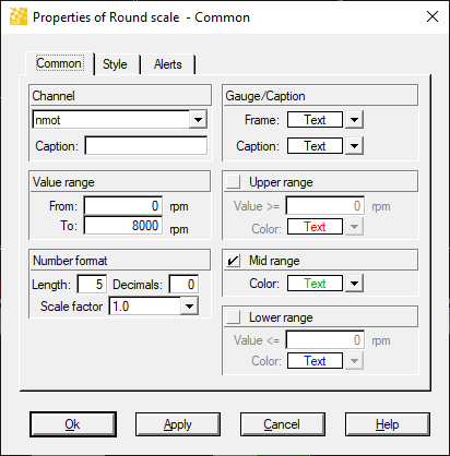
- Channel: Defines the channel data that the element will present
- Caption: Allows an alternate 'channel name' to be displayed
- This is useful in the event the measured channel name is not descriptive / long
- Number Format: Defines the number of digits, number decimals, and scaling that will be used
- Gauge/Caption: Control the base colors of the display element
- Upper/Mid/Lower Range: Control the color of the display element based on the current cursor position value of the channel.
Round Scale Style Settings
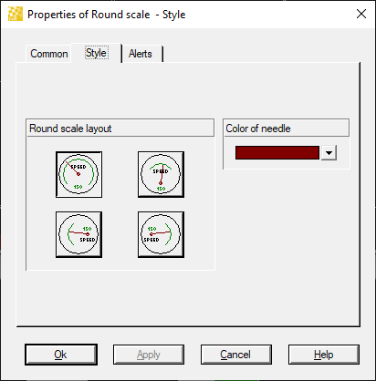
- These are self explanatory
Round Scale Alert Settings
The Round Scale can be configured to visually alert the user based on the channel value.
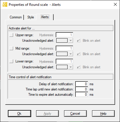
- Hysteresis: the value the channel must change in order to clear a triggered alert
- Example Engine Water Temperature: Hysteresis value = 2 and Upper range = 100
The Alert will trigger when the channel value goes above 100
The Alert will clear when the channel value goes below (100 - 2) = 98 - Upper/Mid/Lower Range: Toggle alerts based on the values on the Common Settings screen.
- Time Controls: Define time based automatic clearing of alerts or retriggers
Bit Panel
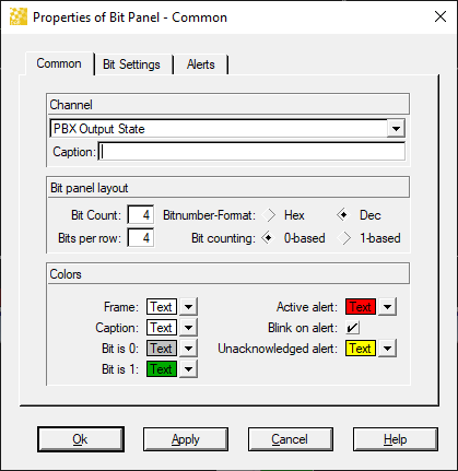
Bit Panel Common Settings
The Bit Panel can be configured with the following settings:
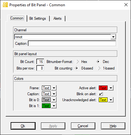
- Channel: Defines the channel data that the element will present
- Caption: Allows an alternate 'channel name' to be displayed
- This is useful in the event the measured channel name is not descriptive / long
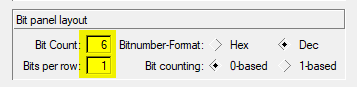
- Bit Panel Layout: Control the shape/layout of the bit panel
- Colors: control the Bit Panel level color settings (can be override on the Bit Settings tab)
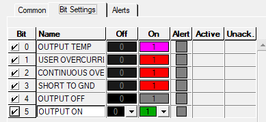
Bit Panel Style Settings
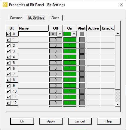
- Overrides for individual bits
- Provide the displayed name / color settings for each bit.
Bit Panel Alert Settings
The Bit Panel can be configured to visually alert the user based on the channel value.
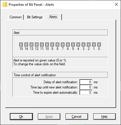
- Alert: Define which bits provide alerts
- Time Controls: Define time based automatic clearing of alerts or retriggers.
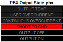
Advanced Bit Panel Usage - PBX Output State
Using PBX Output State as an example, you can define the Bit Panel to present the Output State of a PBX output in a user friendly way:
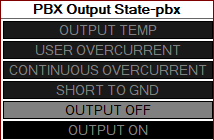
Tutorial:
Step 1:
- Create a filter/default Math Function:
2 ^ ({Default} + 4) - Name it "pbx"
Step 2:
- Add a Bit Panel to your Instrument Panel
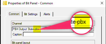
Step 3:
- Define the name of your channel
- Add the text "-pbx" to the name (this applies the Default channel)
Step 4:
- Configure the panel layout and Bit Settings